


Jst Gain Reduction Crack 14 <720p>
| Change | How It Helps | |--------|--------------| | Use a larger‑pitch connector (e.g., 2.0 mm JST‑XH) for high‑stress cables. | Reduces pin‑to‑pin stress, easier to crimp reliably. | | Add a secondary ground clip (e.g., a screw terminal) to share the return current. | Lowers the load on any single ground pin, decreasing the chance of gain loss. | | Route the cable with a bend radius ≥ 3× the outer diameter. | Minimizes flex on the connector. | | Apply a conformal coating over the connector housing (if environmental exposure is a factor). | Prevents moisture‑induced corrosion that can exacerbate cracking. | | Select “high‑reliability” JST series (e.g., VH‑B, PH‑B) that have reinforced contact plates. | Improves mechanical robustness. |
Prepared as a concise technical briefing for engineers, technicians, and hobbyists who encounter the notorious “JST gain‑reduction crack 14” symptom in low‑level audio or sensor applications. jst gain reduction crack 14
| Step | Action | What to Look For | |------|--------|------------------| | 1. Visual inspection | Use a 10‑20 × magnifier. | Bent pins, cracked plastic, missing latch. | | 2. Wiggle test | Gently flex the cable while monitoring the signal (oscilloscope or audio meter). | Intermittent dips or clicks → pin under stress. | | 3. Continuity / resistance test | Measure resistance between the suspect pin and its counterpart on the board. | > 0.1 Ω (for audio) or > 10 Ω (for low‑current sensor) indicates a bad joint. | | 4. Pull‑test | Apply a known pulling force (≈ 2 N) on the cable while watching the signal. | Signal loss at a specific force = mechanical limit reached. | | 5. X‑ray / CT scan (optional) | For high‑value equipment. | Hidden fractures inside the housing. | | Change | How It Helps | |--------|--------------|
 Sındırgı Hıdırellez Şenlikleri'nde yaşatılan psikolojik harp silahı: Savrancı
 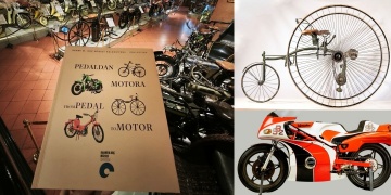 Pedaldan Motora kitabı; bisikletten motosiklete iki tekerli araçların evrimi anlatıyor
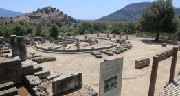
  46. Uluslararası Kazı, Araştırma ve Arkeometri Sempozyumu Programı Açıklandı
 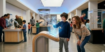 Bilim Müzeleri 'bak ama dokunma' mantığını yıkıyor: Teknoloji Turizmi yükselen trend